1. Specification: 4 Channel (RF4A)

Table 1. Receiver Board
|
|
Description |
Value |
|
1 |
Supply Voltage |
12V DC |
|
2 |
Static Current |
=< 6mA |
|
3 |
Frequency |
315 MHz |
|
4 |
Sensitivity |
>= -105 dB |
|
5 |
Relay Spec. |
10A, 120VAC 10A, 24V DC |
|
6 |
Operating Temperature |
-40 to 80 deg C |
|
7 |
Dimension (w, h, d) |
2.2cm, 3cm, 1.1cm |
|
8 |
Weight (with housing) |
2.5 oz |
Table 2. Transmitter (Remote)
|
|
Description |
Value |
|
1 |
Battery Voltage |
12V (1 piece) |
|
2 |
Dimension (w, h, d) |
1.5cm, 2.5cm, 0.5cm |
|
3 |
Weight (with battery) |
1.2 oz |
|
4 |
Range |
200 m |
2. Procedure to Learn and Erase Codes
a) Press the "Learn" button on the receiver board, the LED will blink indicating the receiver is ready and waiting to learn from transmitter.
b) Adjust jumper according to table 3 to select Output modes.
c) In case a remote is lost and a new remote is to be learned, press "Learn" button for ~10sec until the LED blinks 3 times, which indicates previous learned codes have been erased.
Table 3. Output Mode selection.
|
|
J2 |
J1 |
Output Mode |
|
i |
Open |
Short |
Momentary |
|
ii |
Short |
Short |
Toggle |
|
iii |
Open |
Open |
Latched |
|
iv |
Short |
Open |
ChA, ChB: Momentary ChC, ChD: Toggle |
3.
Encode/Decode:
On receiver board Auto Learning Decoding Scheme has been programmed into the MCU
IC chip, and inside the remote control there is an Encoding IC Chip, 2262. This
set of IC Chips can be used to encode your remote signals so if more than one
remote system are placed close together, they won't interfere each other. You
only need to do little soldering work on the 2262 IC.
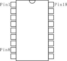
Pin #1 through Pin #8 bring out the Encode function of
your remote transmitter. The receiver board will
automatically learn from Transmitter by pressing a learn button. There are {3 to the power 8} = 6561 different combinations for
encoding/decoding, isn't it cool?
On the back of the board there should be
labels like:
" L" -------- Stands for Low digital state(Close
to GND level).
" H" ------- Stands for High
digital state(9-12V).
"
1" -------- Indicates this is Pin #1.
" 8" -------- Indicates this is Pin
#8.
Just in
case there aren't any labels printed on the PCB board, you still can easily
figure out the "L" and "H" states yourself: After power is hooked up to the
system, use a Voltmeter to measure the contacts on both sides of the column of
eight pins. Voltage level on each side should be consistant. If one side is
"H", the other side should be "L". "H" level
voltage can be measured only when signal is transmitting/receiving.
To figure out Pin #1, look at the front side of 2262 IC Chip. Pin #1 is the
first pin on the left side of the dent.
You don't have to connect all eight
pins to High or Low, even only one pin to H or L will do the
encoding/decoding.
*Note: Sometimes remotes are default encoded to be 00000001, pin 8 is shorted to GND.
Encoded IC has following representation:
If the pin is not shorted to anything, its code value is "0".
If the pin is shorted to "L", its code value is "1",
If the pin is shorted to "H", its code value is a "2".